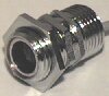
The HX40TRE series sensor is protected by a heavy duty chromed brass housing, with 1/8" or 3mm thick walls. This is a 1/2 inch hex junction using BPT standard British pipe thread. Readily available mounting accessories make this sensor easy to apply and install. The sensor can withstand rain, but water film can block the pores of the protective screen, reducing it's sensitivity until the water has evaporated or been wiped off. It should be shielded from rain. |

In the following, two HX40TR transceivers are placed facing each other at a fixed distance. One transceiver referred to as T1 is exited with various voltage levels, and the opposite transceiver referred to as T2 is used to receive the signal. The graphs below plot the output from T2.
 |
 |
| Above: T1 is exited with a 5Vp-p CMOS square wave oscillating at 40Khz, 100 waves are transmitted. The response as amplitude builds inside the T2 crystal is plotted above. |
Above: 5Vpp CMOS/TTL square wave is applied to T1 at various frequencies. The frequency response is measured across the output wires of T2, and plotted above |
 |
 |
| Above: Continuous excitation voltage oscillating at 40Khz is applied to T1. The T2 resulting amplitude is plotted above. |
The above illustrates how the output of T2 decays as distance increases between T1 and T2. T1 is exited with oscillating voltage, amplitude 28V. |
 |
 |
| Above: T1 was excited with a 30Vp-p 40Khz step input at using signal conditioner HE40SCR, the illustration above shows how long it takes the system to settle on 40Khz. Distance between T1 and T2 is1.5m. |
Above: T1 excitation using HE40SCR 30Vp-p FSK (frequency shift keying) signal, low frequency 38647hz (duration 26 waves) and high frequency 40201hz (duration 26 waves). The response was monitored across output pins of T2, placed 1.5m apart from T1, and plotted as shown above. Note that the ripples are digitization errors. |
 Cable
length between the HE240 series transducers and a signal conditioner, is
left to the user's discretion. At 10m lengths the added environmental
noise and signal reduction at 40khz is insignificant.
Cable
length between the HE240 series transducers and a signal conditioner, is
left to the user's discretion. At 10m lengths the added environmental
noise and signal reduction at 40khz is insignificant.
Beam Pattern
The sensor is located in the locus of the polar plot shown below facing north, maximum signal strength is along the 0 degree axis. As the observer with the measuring instruments moves east and west i.e. perpendicular to the 0 line signal strength degrades. The beam pattern character line shown below represents observation angles where signal has degraded by 6 decibels.
Microchip PIC interface suggestionsThe following example, shows how the PIC16C622 and the PIC16C71 can be interfaced to the HE2XX series transducers. For 40Khz transducers C1 an C2 should be about 2nF, R1 about 3Kohms and R2 about 5Kohms. R3 sets the level for the analog comparator of the PIC16C622 and should be high, say 50Kohm. If the A/D converter of the PIC16C71 is being used, R3 should be removed. There is an error in the schematic on the right, capacitors marked 2.2pF on the input and output of the operational amplifier, should be marked C1 and C2 respectively. The 4.7k ohm resistor at the input of the opAmp should be marked R1. |
 |
ATMEL AVR interface suggestionsThe following example, shows how the AT90S2313 microcontroller can be interfaced to the HE2XX series transducers. For 40Khz transducers C1 an C2 should be about 2nF, R1 about 3Kohms and R2 about 5Kohms. R3 sets the level for the internal analog comparator of the AT90S2313 and should be high, say 50Kohm. There is an error in the schematic on the right, capacitors marked 2.2pF on the input and output of the operational amplifier, should be marked C1 and C2 respectively. The 4.7k ohm resistor at the input of the opAmp should be marked R1. |
 |
INTEL 8051 interface suggestionsThe following example, shows how the INTEL 8051 microcontroller can be interfaced to the HE2XX series transducers. For 40Khz transducers C1 an C2 should be about 2nF, R1 about 3Kohms and R2 about 5Kohms. R3 sets the level for the analog comparator and should be high, say 50Kohm. There is an error in the schematic on the right, capacitors marked 2.2pF on the input and output of the operational amplifier, should be marked C1 and C2 respectively. The 4.7k ohm resistor at the input of the opAmp should be marked R1.
|
 |
Electrical Specifications HX40TR
| Parameters | Values | Units |
| Operating Frequency | 39 | kHz |
| Input Voltage | 20 (max) | Volts (RMS) |
| Output (SPL) @20V | 118 | db |
| Receive (Sensitivity) | -56 | db/V/Ubar |
| Impedance | 300 | ohm |
| Beam Angle | ±12 | degrees |
| Bandwidth | 2 | kHz |
| Settling Decay | 4 | mS |
| Temperature | -40 to 100 | °C |